

1
/
of
2
SYBER SABERS
PROFFIEBOARD V3.9
PROFFIEBOARD V3.9
No reviews
Estimated shipping time: Shipped within 3 days after ordering
Regular price
¥12,000
Regular price
Sale price
¥12,000
Unit price
/
per
Taxes included.
Shipping calculated at checkout.
Couldn't load pickup availability
This is the page for updating savers equipped with Proffieboard V2.2.
This does not support 89Sabers products or products where some circuit boards cannot be changed (the entire chassis must be replaced).
Please contact us in advance using the question form to check whether we can accommodate your request.
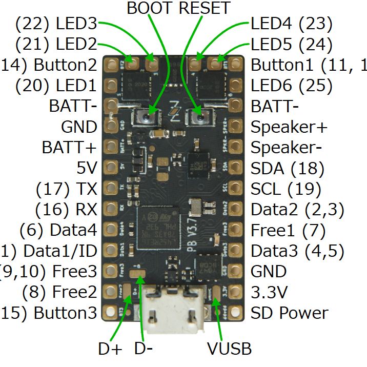
Proffieboard V3.9 is an upgraded version of V2.2, with the following main improvements:
- Increased Memory: Flash memory has been increased to 512KB and RAM to 160KB, allowing for more presets and more complex functions.
- High speed: SDIO is used for SD card access, enabling faster reading speeds.
- USB charging: Now you can charge via a USB port.
- Status LED: On-board LEDs provide visual confirmation of the board's status.
The board comes with a 32GB microSD card made by KIOXIA (formerly Toshiba Memory) UHS-I Class 10 (maximum read speed 100MB/s).
remarks
- High quality silkscreen printing on each pad.
- Certified ZZ logo included.
- The exchanged V2.2 will be returned together with the product.
- The software (ProffieOS) is the same.
- It will take about 20 days after ordering.
Product Specifications
- 80Mhz ARM processor
- 160kb RAM
- 512kb Flash
- 3 button pads (capacitive touch capable)
- 4 neopixel data pads
- 3 Use-for-anything pads
- 3 serial ports
- 3 I2C ports
- 2 SPI ports
- 6 FETs
- 6-axis motion chip
- 3-watt amplifier (mono)
- S/PDIF or I2S output
- 450mA USB charging
- SDIO sd card reader
- Onboard status LED
- center-board pads for: USB, SWDIO and additional 3.3v capacitor
Share